🗓 2 March 2022
Assignment:
I chose to make a simple exercise to create a PCB board that connects a LED light connected with a light sensor. In order to test the connections, I started with creating the circuit on a breadboard using this Arduino reference. I had to adjust the values of the light sensor in the code, but otherwise it was pretty straight forward.

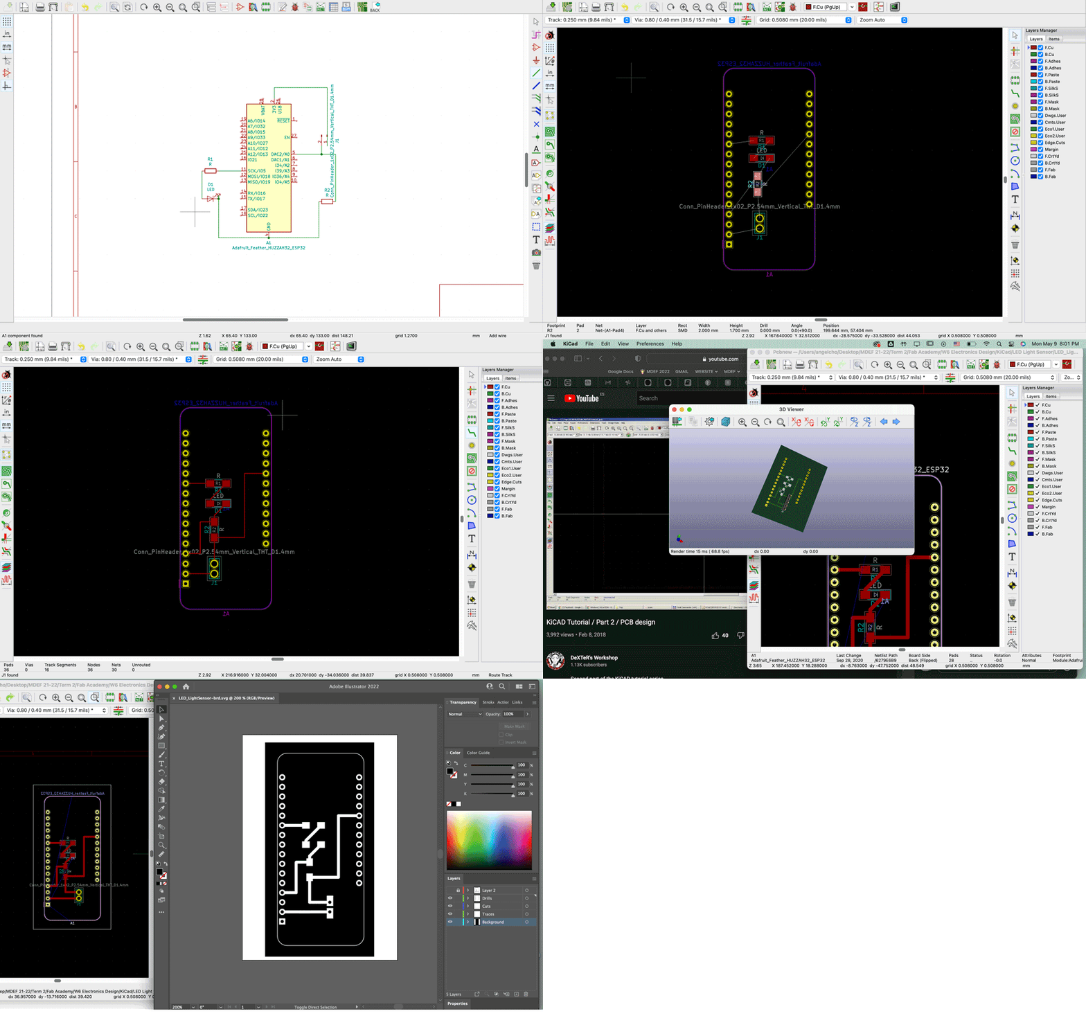
Once I had a successful circuit, I used KiCad to start to recreate it. First, I laid out the components found in the fab library in the schematics window. Then created the connections in layout view. There, I had a bit of trouble with wires crossing and had to return to schematic view and change the pins on the ESP board. I also made the thickness of the connections wider, so it would be surely milled. Finally, I exported the file into a svg file and opened it in illustrator, where I reversed the black and white and assigned layers. Ready to mill my first PCB!

Electronics Design
This week we learned about the different components of basic electronics design. We touched on the different types of resistors, capacitors, diodes, transistors, and regulators. It was a lot of detailed information at once and challenging to follow the details and terminology as a lecture, without hands-on experience. I've worked with some of these elements previously, but not to this extent. And once I start using them, I think much of the information from this lecture will fall into place. The second half of the class was a KiCad electronic design software demo. It was challenging because my software had display issues, so I had to uninstall and reinstall it in the middle of the demo.Assignment:
I chose to make a simple exercise to create a PCB board that connects a LED light connected with a light sensor. In order to test the connections, I started with creating the circuit on a breadboard using this Arduino reference. I had to adjust the values of the light sensor in the code, but otherwise it was pretty straight forward.

Once I had a successful circuit, I used KiCad to start to recreate it. First, I laid out the components found in the fab library in the schematics window. Then created the connections in layout view. There, I had a bit of trouble with wires crossing and had to return to schematic view and change the pins on the ESP board. I also made the thickness of the connections wider, so it would be surely milled. Finally, I exported the file into a svg file and opened it in illustrator, where I reversed the black and white and assigned layers. Ready to mill my first PCB!

